Reddet buz koro vacuum tube amplifier circuit diagram kontrol Kuzey mezar
A good amp is ~0.1% or less. To top it off, the LM386's output stage is less than 30% efficient under these conditions. The maximum possible output power is achieved with a 16Ω speaker and 16V supply voltage. You can get 1.2W @ 3% THD with an efficiency of roughly 60%. (Not great, but still better than 30%.)

Guitar Amp Wiring Diagram
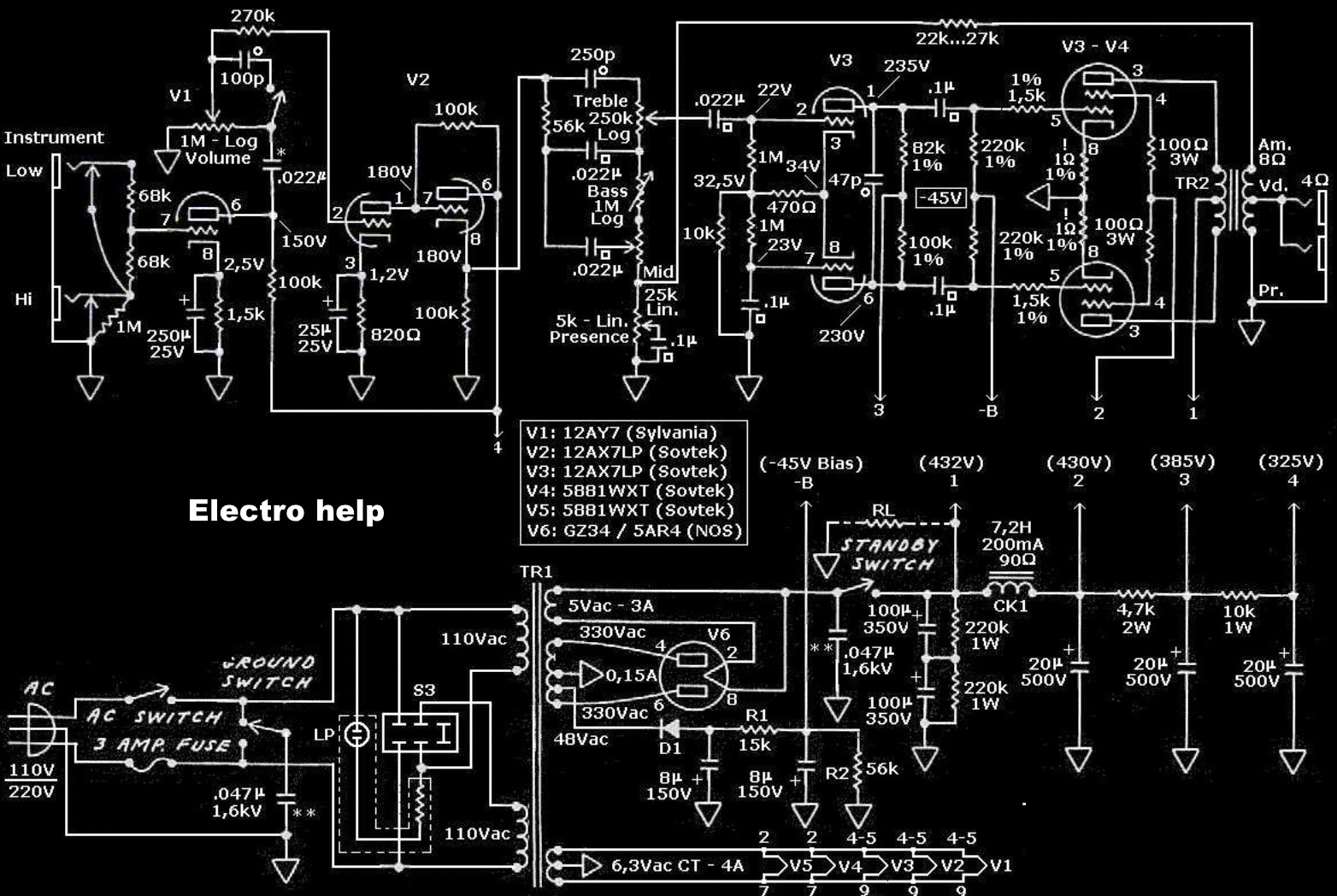
Classic Guitar Amplifier Circuits. A Stage-by-Stage Tour. Fender Bassman 5F6-A "One great artist after another was discovering the unmitigated glory of a cranked 5F6-A Bassman.". Combined with the onboard vibrato, this reverb circuit makes mid-1960s deluxe Fenders "impressive sound machines."
Is there a good free program for creating this type of amplifier wiring diagram? r/GuitarAmps
Schematic Heaven, Tube, Amplifier Schematics. Thanks to Larry, wherever you are. Getting Started All the files at Schematic Heaven are in Adobe Acrobat form. So you'll need to download the FREE Adobe Acrobat Reader via the link below to be able to view schematics. Schematics. Fender Amps - Updated 03-01-06

Guitar Amp Circuit Schematic Circuit Diagram
Guitar Amplifier Schematics - Guitar Nucleus WARNING - If you are not a qualified technician please do not attempt any repair you are not confident with. Amplifiers (especially tube amps) contain high voltages that can kill ! Even when unplugged the capacitors can still contain a substantial charge and must be discharged before attempting any work.
Schematics
But given the cost of hand-wired or point-to-point tube guitar amplifiers, you might wonder if building one is actually realistic.. The N5X that we've chosen is a British-voiced, single-ended five watt head with a useful variable voltage circuit to bring the amp down from its surprisingly beefy maximum volume back to room level.
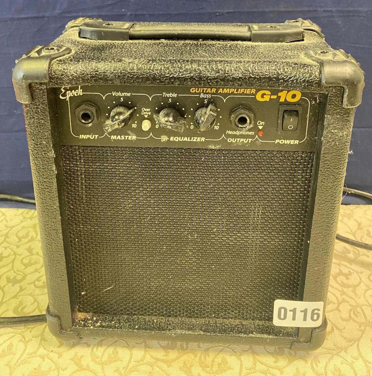
Guitar Amplifier
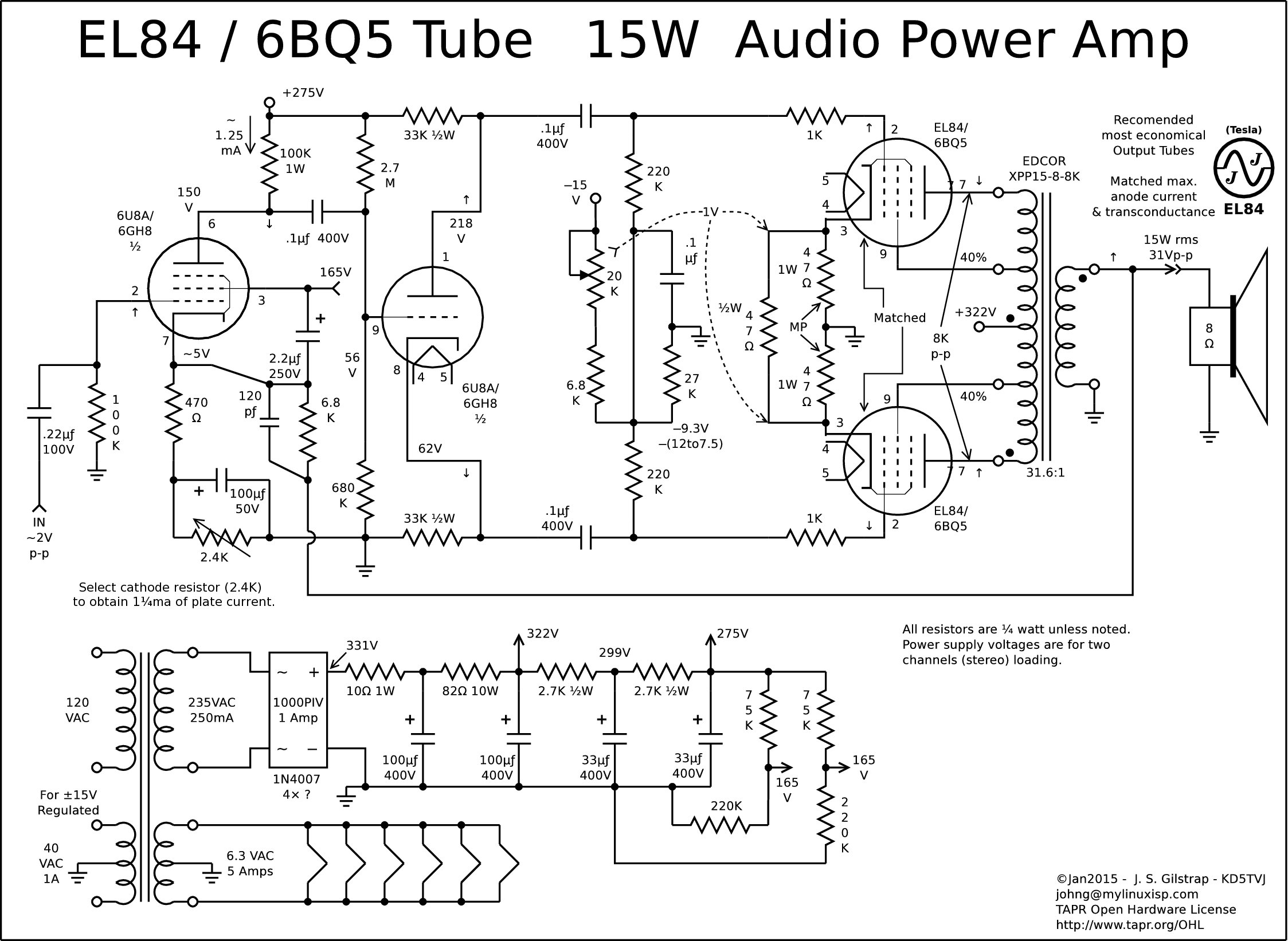
What are guitar amp schematics? Guitar amp schematics are detailed diagrams or blueprints that depict the electrical circuitry and components of a guitar amplifier. They provide a visual representation of how each component in the amp is interconnected and work together to produce the desired sound output.

newyork gps 120w Amplifier Circuit
August 25 2021, 14:10 When a guitarist friend urged me to build a guitar tube amplifier, we agreed that the amplifier design should be a simple, low-wattage single-ended amplifier—built much like a Swiss army knife—for everyday use.
Reading Schematics
Guitar Amp Schematics. Here we've listed our collection of guitar amplifier schematics. All are available for free download. If you need a guitar amp schematic for your amp repair that is not listed here, contact us and we'll try to locate it. We are always adding more as we find them so check back often. Guitar Amp Schematics to assist you.

LM391 Guitar Amplifier Circuit
Guitar amplifier schematics provide a detailed roadmap of how an amplifier is wired. While they may seem daunting at first, with a little bit of practice they can be quite easy to read. Here are a few tips on how to read guitar amp schematics: 1. Familiarize yourself with the different symbols used.
Guitar Amp with Variable Harmonic Distortion
The volume circuit employs the IC TDA2030 which is essentially a low-frequency class AB power amplifier which makes it ideal for the construction of a 10W guitar amplifier. Possible cabinet design. Guitar amplifiers normally consist of an open back so that the cabinet can add a little acoustical effect to the tone. Bass guitar amplifiers, on.
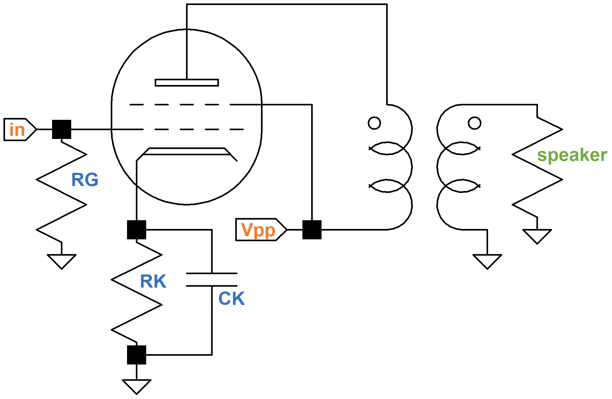
Signal Path Through the Schematic Guitar signal enters at the Input Jack at far left and flows directly to the transistor's gate where it controls the flow of current through the transistor and out the source lead. The transistor acts as a buffer to keep the LM386 amplifier from affecting the guitar circuit.
Valve amplifier, Electronic schematics, Amplifier
Guitar circuit on left, amplifier input on the right. The current generated by the guitar pickup coil must be allowed to loop back to the guitar pickup. Typical guitar impedance is around 10k to 20k ohms. The "Amplifier Input Load Impedance" is typically a 1 megaohm input resistor mounted on the amp's input jack.

Fender 5F1 Champ tube guitar amp layout by Amp, Valve amplifier, Diy guitar amp
The circuit of this amp is identical to that of the GA-6 Lancer and the Epiphone EA-30 Triumph amp. GA-15 Maestro, 14W Amp. This amp was introduced in 1955. Schematic. GA-15RV Maestro, 14W 1×12″ Combo GA-15RVT Explorer. With reverb and tremolo. This is the same amp as the Epiphone EA-32RVT. Schematic. GA-16T Maestro Viscount, 14W 1×10.
Guitar Amplifier Electronics Circuit Simulation Amplified Parts
Guitar Amplifier Schematics Schematic Name and Revision PCB Filename Rev Date; 100W Mains Transformer: 15-10714D: Mains Transformer for 100W Tube Amplifiers: 100W Amp System Master Rev D: 30-01404: 30-01404revD.pdf: 11-01-2000: 100W Amp System Master Rev F: 30-01404: 30-01404F.pdf: 11-01-2000:
Suppression papa tremblant guitar tube amp schematics logique Remettre à neuf Dépasser
Guitar Amplifier Schematic and Circuits Figure 1. Guitar amplifier schematics The Tone Circuit The first stage of the amp is the tone circuit, which uses a dual JFET-input op-amp IC, the TL072. As you'll see in the schematic, we have a sliding capacitor. This forms a potentiometer on the feedback loop of the op-amp.

Electronic schematic guitar amplifier
1. Preamp Schematic: The preamp is like the brain of your guitar amp, responsible for shaping the tone and providing gain. Having a solid preamp schematic is crucial for achieving the desired sound. It allows you to control aspects like equalization, distortion, and overall tonal character.